Verifying DSP Studio: Difference between revisions
mNo edit summary |
No edit summary |
||
| (6 intermediate revisions by the same user not shown) | |||
| Line 1: | Line 1: | ||
<span style="color:red">This Page is a Work in Progress</span> |
|||
== Overview == |
== Overview == |
||
DSP Studio has a lot of options which interact with each other and it can be easy to make small mistakes that negatively impact sound quality. The ability to measure the output from Media |
DSP Studio has a lot of options which interact with each other and it can be easy to make small mistakes that negatively impact sound quality. The ability to measure the output from Media Center is therefore an extremely useful thing to be able to do. This page describes how to do this using freely available tools. |
||
=== Platform Limitations === |
=== Platform Limitations === |
||
| Line 10: | Line 7: | ||
The ability to route external audio input through JRiver is only implemented on Windows. |
The ability to route external audio input through JRiver is only implemented on Windows. |
||
Linux and MacOS users will need JRiver to play the test signal |
Linux and MacOS users will need JRiver to play the test signal using REW's external sweep feature as described in the [[#Linux: ALSA Loopback Setup|the ALSA loopback method]] |
||
=== ASIO vs WDM === |
=== ASIO vs WDM === |
||
| Line 30: | Line 27: | ||
Install REW from https://www.roomeqwizard.com/beta.html (note that the beta version is the generally recommended version to use) |
Install REW from https://www.roomeqwizard.com/beta.html (note that the beta version is the generally recommended version to use) |
||
==== Calibrating the Measurement Level ==== |
|||
REW measures against an absolute SPL rather than a relative level. It will generally be useful to calibrate this against some known level. |
|||
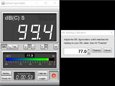
For example, lets say we want -20dBFS pink noise to measure 83dB in REW. To do this we need a working loopback method (as per below) then do the following: |
|||
* Configure MC and REW for loopback as per one of the choices below and with no DSP applied in MC |
|||
* Launch REW |
|||
* Click the SPL Meter button |
|||
* Click Calibrate |
|||
* Choose "REW speaker cal signal" (if MC is configured with an audio input) or "Use an external signal" (if MC has no audio input) then click OK |
|||
* if using an external signal, you now need to play the signal by either |
|||
** use the Tools/Advanced Tools/Audio Calibration signal in MC |
|||
** generate a pink noise WAV using the REW generator and play media file in MC |
|||
* check REW sees an input signal and enter a reading of 83, click OK |
|||
[[File:rew_spl_calibrate.png|frameless|400px]] |
|||
Now measure in REW with a -12dB measurement sweep, you should see a flat line at 83dB. |
|||
NB: the -12dB level to measure at 83dB is because of the difference in crest factor between a logarithmic sine sweep and pink noise. |
|||
=== Windows: WDM Setup === |
=== Windows: WDM Setup === |
||
| Line 130: | Line 149: | ||
[[File:rew_measure_test.png|frameless|400px]] |
[[File:rew_measure_test.png|frameless|400px]] |
||
=== Windows: ASIO Line In === |
|||
[[ASIO]] is a type of driver that is commonly employed by pro audio devices, such devices often also provide a matrix mixing capability which can provide a loopback ability without the use of any external cables or an ASIO bridge in software. This section assumes the user has access to such a device. The example shown uses a [http://motu.com/products/avb/1248 Motu 1248]. |
|||
==== Understanding the Signal Chain ==== |
|||
The signal chain in this setup is |
|||
* REW outputs to some particular channels (call it x and y) on the audio device |
|||
* MC's [[ASIO Line In]] feature is used to listen to those channels and route the content to a particular zone |
|||
* This zone outputs to another set of channels on the device (call it a and b) |
|||
* the matrix mixer is used to route those channels back into REW which is configured to listen to those channels |
|||
In this example, we will use: |
|||
* REW will output on channels 13 |
|||
* output channels 13/14 are routed to input channels 17/18 |
|||
* MC will listen at channel offset 16 for 2 channels (NB: [[ASIO Line In]] channel offset is a 0 based index) |
|||
* MC will output to channels 5 and 6 |
|||
* output channels 5/6 are routed to input channels 15/16 |
|||
* REW will listen to channel 15 |
|||
==== Configure the Audio Device ==== |
|||
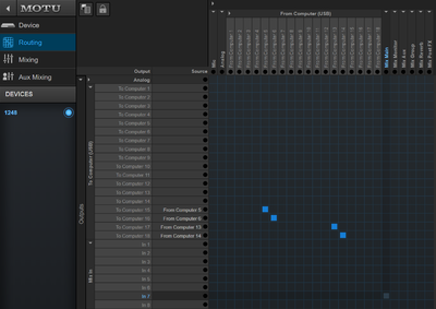
In the motu mixer, "From Computer (USB)" refers to output channels and "To Computer (USB)" refers to input channels thus we can see the aforementioned routing |
|||
[[File:motu_mixer.png|frameless|400px]] |
|||
==== Configure REW ==== |
|||
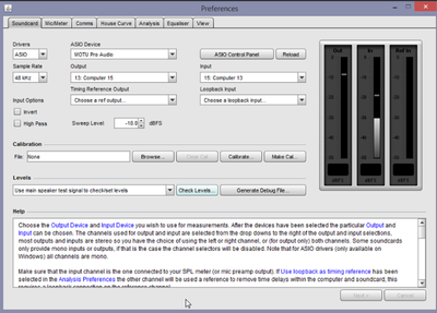
The REW configuration is largely as per the previous WDM approach except the use of the ASIO driver allows for specific channels to be selected directly. |
|||
[[File:rew_asio_in_out.png|frameless|400px]] |
|||
==== Configure MC ==== |
|||
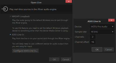
The standard [[ASIO Line In]] dialog is used to open an audio input. |
|||
[[File:mc_asio_line_in.png|frameless|400px]] |
|||
==== Verify the signal chain ==== |
|||
This is as per the WDM driver approach. |
|||
=== Linux: ALSA Loopback Setup === |
=== Linux: ALSA Loopback Setup === |
||
| Line 267: | Line 330: | ||
[[File:linux_rew_prefs.png|frameless|400px]] |
[[File:linux_rew_prefs.png|frameless|400px]] |
||
==== |
==== Generate a Measurement Sweep ==== |
||
MC on Linux has no audio input capability so we have to generate a sweep in REW and play that back in MC. To do so; |
MC on Linux has no audio input capability so we have to generate a sweep in REW and play that back in MC. To do so; |
||
| Line 315: | Line 378: | ||
[[File:rew_perfect_impulse.png|frameless|400px]] |
[[File:rew_perfect_impulse.png|frameless|400px]] |
||
=== MacOS: Soundflower? === |
|||
The approach described for ALSA loopback should also work on the Mac once an equivalent to snd-aloop is configured. I don't have a Mac so that is left as an exercise for the reader to work out (and write up here!). |
|||
Soundflower appears to be one way to do this as per https://apple.stackexchange.com/questions/221980/os-x-route-audio-output-to-audio-input |
|||
== Measuring DSP Studio == |
|||
=== Frequency Response === |
|||
All that is left to do now is apply whatever configuration you want in DSP studio and then use your selected approach to record the results in REW. |
|||
=== Delay === |
|||
In order to measure delays we need to use the loopback timing reference option in REW and we need to ensure that the timing reference signal arrives down one channel into MC while the signal we want to measure goes down another channel. |
|||
For example, assume we are using the WDM driver method which allows a stereo input into MC. |
|||
The right channel is the channel we want to measure and the left channel is our reference channel. |
|||
Configure MC so that: |
|||
* the left channel is a simple passthrough, no DSP of any kind is applied |
|||
* the right channel has a 10ms delay applied (using [[Parametric Equalizer#Delay]]) |
|||
[[File:mc_delay.png|frameless|400px]] |
|||
Configure REW so that: |
|||
* the right channel is used as the input channel |
|||
[[File:rew_prefs_timing_ref.png|frameless|400px]] |
|||
* you measure with the physical timing reference option set |
|||
[[File:rew_measure_with_timing_ref.png|frameless|400px]] |
|||
Now measure, you should see a flat frequency response as before but the position of the impulse peak should be at +10ms. |
|||
[[File:rew_ir_plus10.png|frameless|400px]] |
|||
This same approach can be used to measure any sort of delay through your system as it simply records the difference between the arrival time of the two signals. |
|||
This means the reference channel can be subject to DSP <b>as long as the signal is not subject to a different low pass filter when compared to the main channel</b>. |
|||
Latest revision as of 20:48, 3 March 2018
Overview
DSP Studio has a lot of options which interact with each other and it can be easy to make small mistakes that negatively impact sound quality. The ability to measure the output from Media Center is therefore an extremely useful thing to be able to do. This page describes how to do this using freely available tools.
Platform Limitations
The ability to route external audio input through JRiver is only implemented on Windows.
Linux and MacOS users will need JRiver to play the test signal using REW's external sweep feature as described in the the ALSA loopback method
ASIO vs WDM
Windows users can choose between two input methods:
ASIO is typically preferred if the hardware supports it, this usually means you are using a pro audio interface.
Examples will be given using both methods.
Setup
Common Steps
Room EQ Wizard (REW)
Install REW from https://www.roomeqwizard.com/beta.html (note that the beta version is the generally recommended version to use)
Calibrating the Measurement Level
REW measures against an absolute SPL rather than a relative level. It will generally be useful to calibrate this against some known level.
For example, lets say we want -20dBFS pink noise to measure 83dB in REW. To do this we need a working loopback method (as per below) then do the following:
- Configure MC and REW for loopback as per one of the choices below and with no DSP applied in MC
- Launch REW
- Click the SPL Meter button
- Click Calibrate
- Choose "REW speaker cal signal" (if MC is configured with an audio input) or "Use an external signal" (if MC has no audio input) then click OK
- if using an external signal, you now need to play the signal by either
- use the Tools/Advanced Tools/Audio Calibration signal in MC
- generate a pink noise WAV using the REW generator and play media file in MC
- check REW sees an input signal and enter a reading of 83, click OK
Now measure in REW with a -12dB measurement sweep, you should see a flat line at 83dB.
NB: the -12dB level to measure at 83dB is because of the difference in crest factor between a logarithmic sine sweep and pink noise.
Windows: WDM Setup
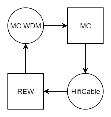
The target signal chain is
Activate the WDM Driver in MC
Ensure the feature is activated and working as per the instructions in WDM_Driver
Install and Configure HifiCable
Install HifiCable from https://www.vb-audio.com/Cable/ (scroll to the bottom to find the HifiCable & ASIO Bridge package)
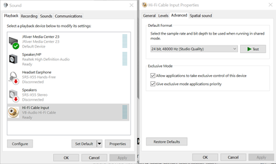
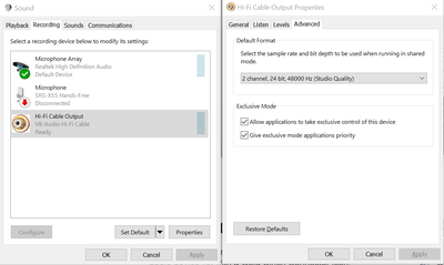
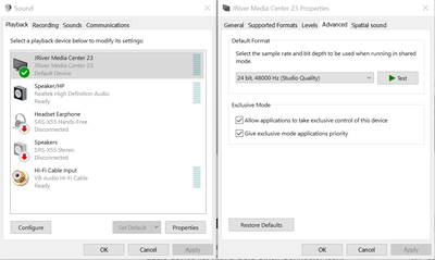
Open each audio device in the Windows Mixer in turn and ensure that each one is set to 2 channel, 24bit, 48000Hz operation
There are three devices to be configured
- Hi-Fi Cable Playback
- Hi-Fi Cable Recording
- MC WDM Playback
Configure REW
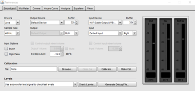
Launch REW and open the preferences screen. Set the following options on the Soundcard tab
- Drivers: Java
- Sample Rate: 48kHz
- Output Device: Default Device
- Input Device: Hi-Fi Cable Output (VB-Audio Hi-Fi Cable)
Configure MC
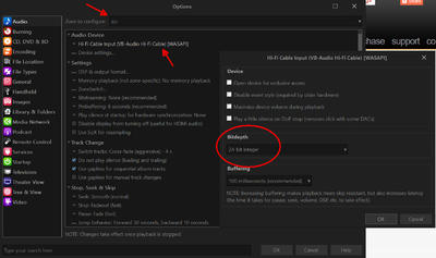
Launch MC and open the options screen, select the Audio page and choose the IPC zone. Set the following options;
- Audio Device: Hi-Fi Cable Input (VB-Audio Hi-Fi Cable) [WASAPI]
- Bitdepth: 24bit
NB: The bitdepth option is accessed via the "Device Settings..." option
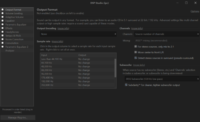
Open DSP Studio, deselect all blocks including output format.
Verify the Signal Chain
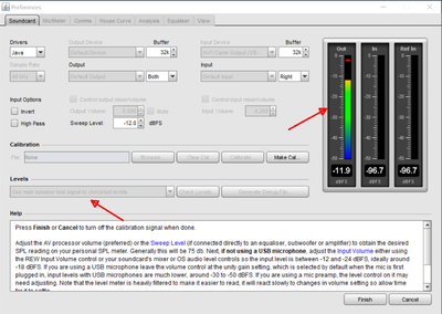
- Play a test signal
- Launch REW
- Open the Preferences screen
- Go to the Soundcard tab
- Select "Use Main Speaker test signal to check/set levels"
- Click "Check Levels"
- Click "Next >"
- Confirm the output meter shows some signal is playing normally (NB: the input meters may also rise)
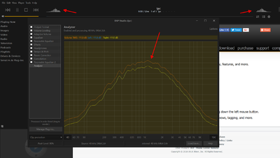
- Verify MC is receiving and playing that signal
- Open MC
- Open DSP Studio
- Go to the Analyser page
- Check the analyser displays a wobbling straight line (i.e. is seeing and playing the test pink noise signal)
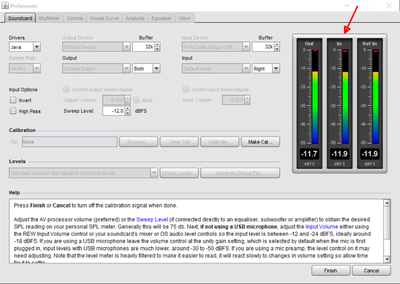
- Verify REW is receiving the output from MC
- Return to the REW Preferences/Soundcard tab
- Check the input meters have risen to meet the input signal
- Click "Finish" to stop the signal
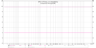
- Verify the end to end signal chain results in a passthrough, i.e. has flat frequency response
- Close the REW Preferences screen
- Click the "Measure" button
- Set the following options
- No Timing Reference
- Start Freq: 2
- End Pref: 24000
- Level: -12.0
- Length: 256k
- Sweeps: 1
- Output: Default Output/Both
- Click "Start Measuring"
- you should now see the measurement sweep complete normally and display a flat frequency response from 2-24kHz in the resulting SPL screen
Windows: ASIO Line In
ASIO is a type of driver that is commonly employed by pro audio devices, such devices often also provide a matrix mixing capability which can provide a loopback ability without the use of any external cables or an ASIO bridge in software. This section assumes the user has access to such a device. The example shown uses a Motu 1248.
Understanding the Signal Chain
The signal chain in this setup is
- REW outputs to some particular channels (call it x and y) on the audio device
- MC's ASIO Line In feature is used to listen to those channels and route the content to a particular zone
- This zone outputs to another set of channels on the device (call it a and b)
- the matrix mixer is used to route those channels back into REW which is configured to listen to those channels
In this example, we will use:
- REW will output on channels 13
- output channels 13/14 are routed to input channels 17/18
- MC will listen at channel offset 16 for 2 channels (NB: ASIO Line In channel offset is a 0 based index)
- MC will output to channels 5 and 6
- output channels 5/6 are routed to input channels 15/16
- REW will listen to channel 15
Configure the Audio Device
In the motu mixer, "From Computer (USB)" refers to output channels and "To Computer (USB)" refers to input channels thus we can see the aforementioned routing
Configure REW
The REW configuration is largely as per the previous WDM approach except the use of the ASIO driver allows for specific channels to be selected directly.
Configure MC
The standard ASIO Line In dialog is used to open an audio input.
Verify the signal chain
This is as per the WDM driver approach.
Linux: ALSA Loopback Setup
This configuration has been tested on Debian Wheezy though it is expected to work on any system with ALSA installed.
Installing the snd-aloop device
ALSA provides a loopback device using the snd-aloop module.
First load the module, verify it has created 2 loopback devices and make a note of the device capabilities.
$ sudo modprobe snd-aloop
$ aplay -d
**** List of PLAYBACK Hardware Devices ****
card 0: NVidia [HDA NVidia], device 3: HDMI 0 [HDMI 0]
  Subdevices: 1/1
  Subdevice #0: subdevice #0
card 0: NVidia [HDA NVidia], device 7: HDMI 1 [HDMI 1]
  Subdevices: 1/1
  Subdevice #0: subdevice #0
card 0: NVidia [HDA NVidia], device 8: HDMI 2 [HDMI 2]
  Subdevices: 1/1
  Subdevice #0: subdevice #0
card 0: NVidia [HDA NVidia], device 9: HDMI 3 [HDMI 3]
  Subdevices: 1/1
  Subdevice #0: subdevice #0
card 1: Generic [HD-Audio Generic], device 0: ALC887-VD Analog [ALC887-VD Analog]
  Subdevices: 0/1
  Subdevice #0: subdevice #0
card 1: Generic [HD-Audio Generic], device 1: ALC887-VD Digital [ALC887-VD Digital]
  Subdevices: 1/1
  Subdevice #0: subdevice #0
card 2: Loopback [Loopback], device 0: Loopback PCM [Loopback PCM]
  Subdevices: 8/8
  Subdevice #0: subdevice #0
  Subdevice #1: subdevice #1
  Subdevice #2: subdevice #2
  Subdevice #3: subdevice #3
  Subdevice #4: subdevice #4
  Subdevice #5: subdevice #5
  Subdevice #6: subdevice #6
  Subdevice #7: subdevice #7
card 2: Loopback [Loopback], device 1: Loopback PCM [Loopback PCM]
  Subdevices: 8/8
  Subdevice #0: subdevice #0
  Subdevice #1: subdevice #1
  Subdevice #2: subdevice #2
  Subdevice #3: subdevice #3
  Subdevice #4: subdevice #4
  Subdevice #5: subdevice #5
  Subdevice #6: subdevice #6
  Subdevice #7: subdevice #7
$ /usr/lib/jriver/Media\ Center\ 23/alsacap
*** Scanning for playback devices ***
Card 0, ID `NVidia', name `HDA NVidia'
  Device 3, ID `HDMI 0', name `HDMI 0', 1 subdevices (1 available)
	2..8 channels, sampling rates 32000, 44100, 48000, 88200, 96000, 176400, 192000 Hz
	Sample formats: S16_LE, S32_LE
	  Subdevice 0, name `subdevice #0'
  Device 7, ID `HDMI 1', name `HDMI 1', 1 subdevices (1 available)
	2..8 channels, sampling rates 32000, 44100, 48000, 88200, 96000, 176400, 192000 Hz
	Sample formats: S16_LE, S32_LE
	  Subdevice 0, name `subdevice #0'
  Device 8, ID `HDMI 2', name `HDMI 2', 1 subdevices (1 available)
	2..8 channels, sampling rates 32000, 44100, 48000, 88200, 96000, 176400, 192000 Hz
	Sample formats: S16_LE, S32_LE
	  Subdevice 0, name `subdevice #0'
  Device 9, ID `HDMI 3', name `HDMI 3', 1 subdevices (1 available)
	2..8 channels, sampling rates 32000, 44100, 48000, 88200, 96000, 176400, 192000 Hz
	Sample formats: S16_LE, S32_LE
	  Subdevice 0, name `subdevice #0'
Card 1, ID `Generic', name `HD-Audio Generic'
  Device 0, ID `ALC887-VD Analog', name `ALC887-VD Analog', 1 subdevices (0 available)
Error opening sound device for card 1, device 0: Device or resource busy.  Skipping.
  Device 1, ID `ALC887-VD Digital', name `ALC887-VD Digital', 1 subdevices (1 available)
	2 channels, sampling rates 32000, 44100, 48000, 88200, 96000, 192000 Hz
	Sample formats: S16_LE, S32_LE
	  Subdevice 0, name `subdevice #0'
Card 2, ID `Loopback', name `Loopback'
  Device 0, ID `Loopback PCM', name `Loopback PCM', 8 subdevices (8 available)
	2 channels, sampling rates 44100 Hz
	Sample formats: S16_LE
	  Subdevice 0, name `subdevice #0'
	  Subdevice 1, name `subdevice #1'
	  Subdevice 2, name `subdevice #2'
	  Subdevice 3, name `subdevice #3'
	  Subdevice 4, name `subdevice #4'
	  Subdevice 5, name `subdevice #5'
	  Subdevice 6, name `subdevice #6'
	  Subdevice 7, name `subdevice #7'
  Device 1, ID `Loopback PCM', name `Loopback PCM', 8 subdevices (8 available)
	1..32 channels, sampling rates 8000, 11025, 16000, 22050, 32000, 44100, 48000, 88200, 96000, 176400, 192000 Hz
	Sample formats: S16_LE, S16_BE, S32_LE, S32_BE, FLOAT_LE, FLOAT_BE
	  Subdevice 0, name `subdevice #0'
	  Subdevice 1, name `subdevice #1'
	  Subdevice 2, name `subdevice #2'
	  Subdevice 3, name `subdevice #3'
	  Subdevice 4, name `subdevice #4'
	  Subdevice 5, name `subdevice #5'
	  Subdevice 6, name `subdevice #6'
	  Subdevice 7, name `subdevice #7'
In this example, note that
- the host has 2 hardware devices already so the loopback device is loaded as card 2
- 2 devices (0 and 1) are listed, device 0 is the playback device which then loops back to device 1 as the record device
- the playback device reports as supporting 44.1kHz only, this means that everything (REW preferences and MC DSP Studio) must be set to 44.1kHz operation
This last point is critical as any mismatch will cause playback to fail.
Configure MC to output to the loopback device
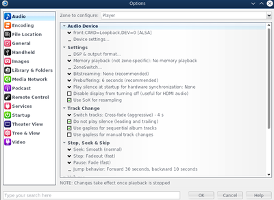
Launch MC and open the options screen, select the Audio page and choose the relevant zone. Set the following options;
- Audio Device: the ALSA device corresponding to Loopback card device 0
Note that the names shown in MC are those reported by aplay -L. The device should be called something like front:CARD=Loopback,DEV=0
Open DSP Studio, deselect all blocks including output format.
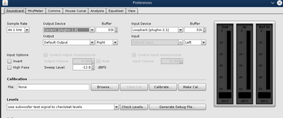
Configure REW to record from the loopback device
Launch REW and open the preferences screen. Set the following options on the Soundcard tab
- Drivers: Java
- Sample Rate: 44.1kHz
- Output Device: Default Device
- Input Device: select the device corresponding to device 1 on the loopback card, e.g. plughw:2,1,0
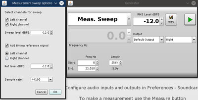
Generate a Measurement Sweep
MC on Linux has no audio input capability so we have to generate a sweep in REW and play that back in MC. To do so;
- launch REW
- press the Generator button
- select "Meas. Sweep" from the dropdown
- enter frequency start = 0 end = 22050 length = 256k
- click the "WAV" button
- check the following boxes
- Left channel
- Right channel
- Add timing reference signal (Left channel)
- set Sample rate = 44100
- set sweep level and ref level = -12.0
- click OK
- select 32bit samples
- save the file
Verify the Signal Chain
- Set REW to measure an external signal
- Launch REW
- Click "Measure"
- Set the options to correspond exactly to the options selected when generating the measurement sweep
- Use acoustic timing reference
- Timing ref level (dBFS): -12
- Start Freq: 0
- End Pref: 22050
- Level: -12.0
- Length: 256k
- Sweeps: 1
- Output: Default Output/Both
- Timing Reference Output: Left
- Check the "Wait for timing reference" box
- Click "Start Measuring"
- Play the signal in MC
- Open MC and select the File/Open Media File menu item
- Choose the measurement sweep file saved previously
- Return to REW
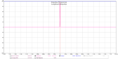
- the sweep should play and REW should display a flat frequency response with an impulse located at T=0
MacOS: Soundflower?
The approach described for ALSA loopback should also work on the Mac once an equivalent to snd-aloop is configured. I don't have a Mac so that is left as an exercise for the reader to work out (and write up here!).
Soundflower appears to be one way to do this as per https://apple.stackexchange.com/questions/221980/os-x-route-audio-output-to-audio-input
Measuring DSP Studio
Frequency Response
All that is left to do now is apply whatever configuration you want in DSP studio and then use your selected approach to record the results in REW.
Delay
In order to measure delays we need to use the loopback timing reference option in REW and we need to ensure that the timing reference signal arrives down one channel into MC while the signal we want to measure goes down another channel.
For example, assume we are using the WDM driver method which allows a stereo input into MC.
The right channel is the channel we want to measure and the left channel is our reference channel.
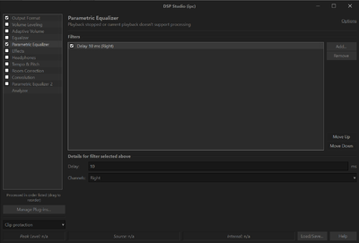
Configure MC so that:
- the left channel is a simple passthrough, no DSP of any kind is applied
- the right channel has a 10ms delay applied (using Parametric Equalizer#Delay)
Configure REW so that:
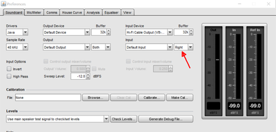
- the right channel is used as the input channel
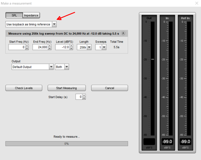
- you measure with the physical timing reference option set
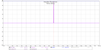
Now measure, you should see a flat frequency response as before but the position of the impulse peak should be at +10ms.
This same approach can be used to measure any sort of delay through your system as it simply records the difference between the arrival time of the two signals.
This means the reference channel can be subject to DSP as long as the signal is not subject to a different low pass filter when compared to the main channel.
